Now, my boss asked if I could develop a device to assist in a lesson concerning binary and computation. I thought for a moment and realized that "Why yes, yes I can." I've always been a fan of near instant feed back. It's mostly why I work with computers. So here's the design needs for now:
1. 8 Bit data entry
2. Display corresponding ASCII character
3. Data entry needs to be easy enough for a child to use.
4. We're not all rich so it needs to be fairly cheap.
So here's the plan:
8 switches of some sort + 1 push button for "Enter" (Multiplexed)
8x8 LED Matrix Display
MSP430Gx2xx (TI Launchpad, for grins)
For the display, we'll use the matrix and we'll drive it with 2 8 bit shift registers (more info) and some AND gates for output enabling. The basic layout in my head looks like this:
 |
| Display Driver |
Notice we feed the Row Select shift register CLK (outer wire at bottom) with the rising edge of the LSB of the Column Select shift register. This will allow us to do entries into the row select only when we're toggling the LSB of the column, this will present some interesting coding challenges.
Originally I didn't have the transistors in there, and then I kinda remembered that the row shift register won't be able to sink the sourced current of the column shift register due to being in high impedance. So we use npn transistors (3904 because I had a bag of them laying around) to sink the current, controlled by the row select shift register, and series in some 500 ohm resistors on the a collector side to protect our LED matrix (which by the way is the most expensive part of this project!)
For the input, due to I/O constraints on the MSP430 (10 pins), I'm thinking we'll use an 8:1 multiplexer which we'll layout kind of like this:
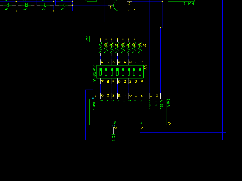 |
| Data Input (8:1 Mutiplexer) |
Notice we use the LSBs of the Column Select shift register to control the select lines of our 8:1 multiplexer, so we can address our 8 switches and to prevent the noise of shifting our select bits in, we'll just turn the OE off and voila no display for a fraction of a second while we poll for data when needed.
Now the MSP430 ties together with these other components to make a near complete schematic.
 |
| Whole circuit |
When the pushbutton on P1.2 (at top, 1 resistor + pushbutton) is pressed, we'll read in the values through the mux, then we'll a display the corresponding ascii character. So in the next post we'll talk about the shortcomings (if I missed something) and the software to drive this groovy display. I may also look into how to get the chip to turn off the display peripherals when it's been inactive for a couple minutes, and other similar things.